Select the Right Blower by Understanding Airflow
Introduction:
You can select the right brushless blower and optimize efficiency for your particular application by first learning the laws determining efficient airflow in your system. These laws will help you to quickly find your ideal operating point, maximize your blower performance and help ensure safe operation. By considering these and other factors you can better ensure your standard or custom model is suited to your performance curves, application and working environment.
#1: Identify Your Application’s Operating Point:
Determine your flow rate
Since different blowers move different amounts of air, learning the laws of how air moves through your blower will help you more quickly determine the size, type, and configuration of your blower.
At this initial stage, you’ll want to start by considering how much air flow (i.e. flow rate) you’ll actually need for your application. Most blower models have a specific air flow range which determines the blower’s air volume. Be sure to account for the most common factor – clogs in the air filter. As the blower’s openings become obstructed over time, the blower’s air volume is impacted, so the design should take that into consideration. Often using electronic speed control, the blower’s performance can be adjusted for varying operating conditions.
Calculate your system’s Flow Resistance
Now we’ll determine your system’s flow resistance by first identifying your system resistance curve (see Figure 1 below). Flow resistance can often be more simply reduced to a pressure drop for a given flow rate, usually following a 2nd-order relationship.
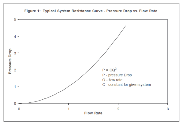 Figure 1: Typical System Resistance Curve – Pressure Drop vs. Flow Rate
Accounting for backpressure from ductwork, filters, obstructions, etc.
The pressure rise provided by the blower matches the pressure loss imposed by the system resistance. This system resistance is often referred to as backpressure or head loss. This is why you’ll want to account for backpressure from your system’s ductwork, filters, obstructions, etc.
Find your desired operating point
Now identify your application’s operating point, using your required flow rate and the flow resistance of your system including the ductwork, filters, obstructions, etc. See Figure 2 below.
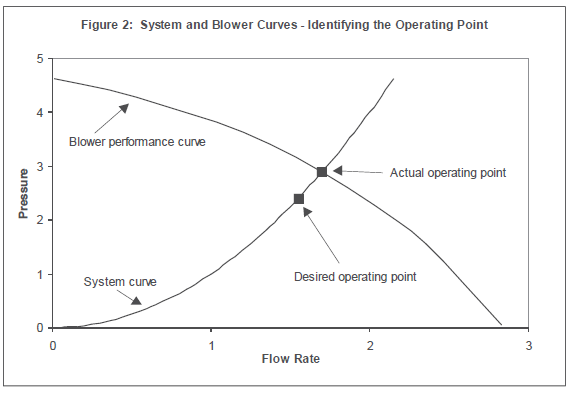
Figure 2: System and Blower Curves – Identifying the Operating Point
Once you know your operating point, you can estimate your blower’s associated system curve by using the simple relationship P=CQ2.
Where:
- P = Pressure drop
- Q = Flow rate
- Which determines the constant C = system curve
Now, graphically overlay the resulting system curve onto a given blower performance curve, looking for the intersection of these two curves. This gives you a more accurate operating point.
How to read a performance curve
Now that you’ve found your operating point, you can begin searching catalogs for blower models. Only consider those with performance curves higher than your operating point, because of blower to blower variation and future advancements with your products. Although we don’t see a lot of variation, sometimes some blowers have a little more/less performance than others. That is why you’ll want to make sure you are not operating at the blower’s maximum performance. You can quickly check their suitability by placing your operating point on a given blower curve and using it to review the system curve.
If you want assistance determining your operating point or other parameters, AMETEK DFS’s applications engineering team is happy to help.
Match your performance to the right blower
It’s important to match your blower’s size to the exact level of performance your application requires. You’ll probably find several models that can achieve your desired performance, but not all will operate with the same efficiency. For example, our chart below can be used to identify the proper blower from AMETEK’s Nautilair® family based on the output of your application as measured in BTUs if you are using our products in a premix combustion system. See Figure 3 below. 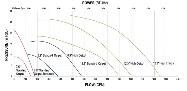
Figure 3: BTU Ranges by Parameter
Your first consideration is to match the air performance of your existing blower. Normally you’ll want to select the blower that delivers the desired performance with the least amount of input power. Typically, the most efficient blower is the one where the system resistance curve intersects the blower curve near the peak efficiency of the blower.
You’ll also need to consider power supply, since different blower motors have different power requirements. What input voltage do you have available for powering the blower? Also consider form factor – the size the motor can fit in. Will a blower of this size fit in your application? Form factor includes all the mechanical elements that go into the mounting and handling, and also air movement.
Other questions to consider when selecting a blower:
- Do I need an on-board controller, or can I provide an external controller?
- Do I need a blower with fast dynamic response?
- Is loudness a major factor?
- Are there any additional features I need, such as a tachometer output, dynamic braking, or speed control functions?
- Is it a problem if the working fluid comes into contact with electronics?
- What are the environmental factors associated with my application?
For help with these and other design elements, you can also make use of our extensive technical resources here at AMETEK DFS or contact us to speak with our applications engineering team.
Adjustable speed control
Does your application require modulating the speed during operation? If so, variable speed brushless DC blowers are engineered to deliver air flow over a large performance range. Having electronic speed control methods enables you to maintain a more constant flow even as system impedance changes such as when the filter begins to clog. Consider using variable speed blowers as a more efficient alternative to conventional speed or two-speed blowers, intake damper systems on fixed-speed blowers, or inverter-driven variable speed blowers.
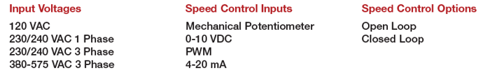
Configurable speed control profiles enable you to set custom speed set points, ramps and more. On some models, you can adjust the speed internally using an on-board potentiometer or with an external PWM or DC control that actively varies blower performance (eliminating a need for complex air intake damper systems). Meanwhile internal electronics convert AC input to DC.
Options for input voltage and control types can make brushless blowers adaptable to a wide variety of applications. Depending on your application, the blower can be configured for either open or closed loop control. In closed loop control, a specific speed control command (e.g. 5vdc) is correlated to a specific blower speed (e.g. 8,000 RPM). If the system resistance (i.e. pressure) changes, the speed will be maintained. By contrast, open loop control allows for the speed to vary according to the system resistance. As an example, AMETEK BLDC blowers have adjustable speed control so you can reach any operating point that lies underneath a given performance curve.
#2: Optimize Your Blower’s Performance:
Determine air density
Determine if your application is within the Standard Atmosphere Table (widely available online); if not, you will need to determine air density. To do this:
- Measure the temperature, barometric pressure, and humidity of the working environment.
- Use a psychrometric chart listing air property for temperature and humidity ranges.
Standard blower or custom-engineered solution?
Will a standard blower be enough for your application or do you need a custom-designed blower? If your application has one or more unique requirements (such as a specification or certification) you may want to ask manufacturers for a bespoke solution.
How long will your blower last?
Brushless DC blowers have the advantage of long life compared to blowers driven by brush motors. Since a brushless motor is electronically commutated, there are no brushes to wear out, which means more time in service and a longer life.
A brush motor’s brushes will eventually wear out, like the brakes on your car. However, brushless motors by design don’t have this wear problem. As a result, the life expectancy of a brushless motor over a brush one could be 10-20x the lifespan across comparable models.
Since long life is one of the main attributes of brushless blower technology, our customers often ask, “How long will it last?” A high-quality blower will have a long lifespan with virtually no maintenance, typically in excess of 20,000 hours. However, there are several factors that influence blower life including:
- Temperature
- Bearing contamination
- Mechanical shock
- Operating point
Temperature: Brushless blowers don’t work as well in hot environments since high temperatures pose a risk to the blower’s internal electronics. Additionally, the deterioration of bearing grease is directly proportional to temperature; the higher the temperature, the shorter the bearing life. While there is no hard limit on bearing temperature, generally cooler is better. Based on your application, there is a point of diminishing returns, so reducing temperature is unnecessary if the blower life is adequate for the application. A good rule of thumb for AMETEK DFS blowers is 45oC maximum ambient temperature, but this can be exceeded with bearings that can withstand high temperature ratings.
Please consult AMETEK DFS engineering for applications involving high temperatures. Ultimately, it is up to the customer to determine whether or not a blower can provide adequate life. Extensive testing is also recommended. Also keep in mind that extreme temperature can cause premature failure of electronics or the motor winding.
Bearing contamination: The introduction of particulate matter increases the rolling friction of the bearing, which in turn increases temperature. Particulates also scar the surface of the bearing raceways and balls, which increases pitting and flaking, further exacerbating the condition. Corrosive gases can react negatively with grease or cause corrosion of the steel in the bearings. Liquids of any kind should be avoided. Water vapor is not a problem as long as it does not condense into liquid water inside the blower.
Mechanical shock: Mechanical shock can cause denting of the bearing’s rolling elements. This results in unwanted noise and can lead to flaking and pitting inside the bearing. Applications that subject the blower to mechanical shock should be thoroughly tested to ensure adequate life.
Operating point: The amount of backpressure a blower works against is another influencing factor in some blower models. The backpressure results in a pressurized blower housing, putting a pressure gradient across the adjacent bearing. The pressure gradient tends to push the grease out and contamination in. At AMETEK we’ve implemented design features to minimize this effect, so you should not be hesitant to operate at high pressure if your application calls for it.
#3: Selecting for Safe Operation:
Safety disclaimer
You must use several safety precautions when using brushless blowers.
NOTE: THE FAILURE TO OBSERVE THE FOLLOWING SAFETY PRECAUTIONS COULD RESULT IN SERIOUS BODILY INJURY, INCLUDING DEATH IN EXTREME CASES.
We recommend that adequate instructions and warnings by the original equipment manufacturers (OEM) should include labels listing the below precautions to end users:
Proper grounding and dangerous materials warning
The motors and/or blowers must be connected to a proper and effective ground or mounted in a manner that will guarantee electrical isolation and insulate the user and others from electric shock. End product design should not rely solely on the primary insulation of the motor.
Standard blowers and/or motors are not designed to handle volatile or flammable materials through the fan system unless specifically designed. Passing combustible gases or other flammable materials through the fan system could result in leakage which could cause a fire or explosion.
These products must not be used in an area contaminated by volatile or flammable materials since sparking is predictable in the normal operation of the motor and may ignite the volatile causing a dangerous explosion.
Custom designs
AMETEK DFS can supply specifically designed motors and blowers for use in handling combustible gases or for use in hazardous duty locations. These specially designed units should only be used in conjunction with combustible gases, which they were specifically designed to handle. The type of gases must be so noted on the product label and in the instructions.
Motor shaft rotation, vacuum/air pressure, sparking and electrical shock
The rotation of the motor shaft, or anything mounted on the shaft, is a potential source of injury and must be considered in the design of your end product. You must provide the necessary guarding or housing as required by the finished product and you must indicate to the user the direction of rotation. Do not remove guard as severe bodily injury may occur to fingers or appendages.
Products incorporating vacuum motors/blowers must be designed so as to prevent the vacuum or air pressure from being concentrated in a manner that can expose the user to injury by coming into contact with any bodily area, such as eyes, ears, mouth, etc.
The motors and/or blowers must not be exposed to moisture or liquid or used outdoors, except in equipment which is specifically designed for outdoor use and meets the appropriate regulatory agency requirements for outdoor use. Moisture or liquid can damage the motor/blower and defeat the electrical insulation resulting in a severe electrical shock to the user.
AMETEK motors/blowers must not be operated above the design voltage. Over voltage conditions can cause excessive speed of the motor and can result in severe electrical shock and/or other traumatic injury to the operator.
Precautions must be exercised to ensure motor leads are properly routed and connected in your equipment. Lead wires must be routed and retained to ensure that they do not become pinched or come in contact with rotating parts during assembly or subsequent operations. Connections must be designed so that proper electrical contact is established, and the connections must be properly insulated.
Disassembly or repairs of AMETEK DFS brushless blowers should not be attempted. If accomplished incorrectly, repairs can create an electrical shock and/or operational hazard. It is recommended that repairs be made only by AMETEK DFS.
If the motor or blower ceases to operate, power must be disconnected before examination and/or removal from the system.
Contact AMETEK DFS to discuss any questionable application before selecting a standard motor or blower.
In setting forth the above listed recommendations with regards to precautionary steps that must be considered, we in no way intend to imply that if these steps are taken a product will meet the applicable safety standards.
AMETEK DFS disclaimer
We at AMETEK DFS are not sufficiently conversant with the specific safety hazards which may be associated with particular products. We can only advise precautions to be employed generally for the safe use of AMETEK DFS products as components.
For testing specifically related to the safety of the product, we recommend that you contact the appropriate regulatory agency as indicated by the type of product being manufactured.
Conclusion
By understanding and determining the factors affecting ideal airflow, you can more easily find the most efficient brushless blower for your application. Understanding the laws governing airflow will not only make your search for the right model easier, but also boost your system performance and safety.